GAS Reducing Valve
manufacturer: Kaiweixi Valve Group Co., Ltd.
Eml: Yannie@kaiweixi.com
Tel: +86(577)67038872
Mob: +86 189 6779 6135(WeChat Same Account)
product drawing
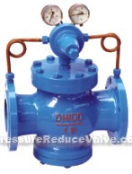
GAS reducing valves
Structural reature and function
This reducing valve belongs to the pilot piston valve. From two parts the main valve and pilot valve. The main valve is mainly constituted by seat, main valve disc, piston and springs.
Pilot valve consists mainly of seat, disc diaphragm, spring, adjust springs etc., Through adjusting spring pressure regulating outlet pressure, using the diaphragm sensing outlet pressure changes,through the pilot valve on-and–off driven piston to adjust the size of the flow area at main valve throttling part, stabilizing and reducing pressure.
This product is mainly used in the gas pipe, such as air, nitrogen, oxygen, hydrogen gas, natural gas, etc.
Dimensions & constructral diagram
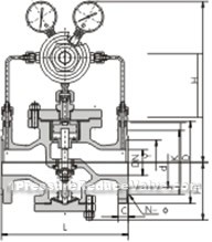
GAS reducing valve constructral diagram
Main technical parameter and performance norm
| Nominal Pressure(Mpa) | 1.6 | 2.5 | 4.0 | 6.4 | 10.0 | 16.0 |
| Casing Body Test Pressure (Mpa)* | 2.4 | 3.75 | 6.0 | 9.6 | 15.0 | 24 |
| Sealing Test Pressure (Mpa) | 1.6 | 2.5 | 4.0 | 6.4 | 10.0 | 16.0 |
| Max. inlet Pressure (Mpa) | 1.6 | 2.5 | 4.0 | 6.4 | 10.0 | 16.0 |
| Outlet Presure Range(Mpa) | 0.1-1.0 | 0.1-1.6 | 0.1-2.5 | 0.5-3.5 | 0.5-3.5 | 0.5-4.5 |
| Pressure Property Deviation (Mpa)△P2P | GB12246-1989 | |||||
| Flow Property Deviation (Mpa)P2G | GB12246-1989 | |||||
| MIin. Pressure Difference (Mpa) | 0.15 | 0.15 | 0.2 | 0.4 | 0.8 | 1.0 |
| Leakage Quantity | X/F(PTFE/ RUBBER):O Y(HARD-SEAL):GB12245-1989 | |||||
Material Oof main parts
| name of parts | material |
| body,bonnet,bottom cap | WCB/FCB* |
| seat disc | 2Cr13/304* |
| cylinder sleeve | 2Cr13/25(hard chrome plating)/304* |
| piston | 2Cr13/ alloy copper/ alloy copper* |
| piston ring | alloy cast iron/ para-position polyphenyl* |
| pilot valve seat, pilot valve rod | 2Cr13/304* |
| diaphragm | 1Cr18Ni9Ti |
| main valve.pilot valve spring | 50CrVA |
| adjustable spring | 60Si2Mn |
| sealing gasket(X/F type) | rubber/ PTFE |
| pilot body,pilot bonnet | 25/304* |
flowrate factor(Cv)
| DN | 15 | 20 | 25 | 32 | 40 | 50 | 65 | 80 | 100 | 125 | 150 | 200 | 250 | 300 | 350 | 400 | 500 |
| Cv | 1 | 2.5 | 4 | 6.5 | 9 | 16 | 25 | 36 | 64 | 100 | 140 | 250 | 400 | 570 | 780 | 1020 | 1500 |
dimensions (PN1.6-4.0)unit:mm
| nominal diameter DN | dimensions | |||
| L | H | Hl | ||
| 1.6/2.5MPa | 4.0MPa | |||
| 15 | 160 | 180 | 290 | 90 |
| 20 | 160 | 180 | 300 | 98 |
| 25 | 180 | 200 | 300 | 110 |
| 32 | 200 | 220 | 300 | 110 |
| 40 | 220 | 240 | 320 | 125 |
| 50 | 250 | 270 | 320 | 125 |
| 65 | 280 | 300 | 325 | 130 |
| 80 | 310 | 330 | 365 | 160 |
| 100 | 350 | 380 | 365 | 170 |
| 125 | 400 | 450 | 475 | 200 |
| 150 | 450 | 500 | 475 | 210 |
| 200 | 500 | 550 | 515 | 240 |
| 250 | 650 | 560 | 290 | |
| 300 | 800 | 705 | 335 | |
| 350 | 850 | 745 | 375 | |
| 400 | 900 | 780 | 405 | |
| 450 | 900 | 730 | 455 | |
| 500 | 950 | 835 | 465 | |
dimensions (PN6.4-16.0)unit:mm
| nominal diameter DN | dimensions | |||
| L | H | Hl | ||
| 6.4MPa | 10.0/16.0MPa | |||
| 15 | 180 | 180 | 300 | 100 |
| 20 | 180 | 200 | 310 | 105 |
| 25 | 200 | 220 | 31 | 120 |
| 32 | 220 | 230 | 310 | 120 |
| 40 | 240 | 240 | 335 | 135 |
| 50 | 270 | 300 | 335 | 135 |
| 65 | 300 | 340 | 340 | 140 |
| 80 | 330 | 360 | 380 | 170 |
| 100 | 380 | 380 | 185 | |
| 125 | 450 | 490 | 215 | |
| 150 | 500 | 490 | 225 | |
| 200 | 550 | 535 | 260 | |
| 250 | 650 | 580 | 310 | |
| 300 | 800 | 725 | 355 | |
| 350 | 850 | 765 | 395 | |
| 400 | 900 | 800 | 435 | |
| 500 | 950 | 855 | 495 | |


