The Modeling and Analysis of CNG engine High based on AMESim
Premix natural gas engines work needed natural gas is low-pressure natural gas, it must pass through the multi-level decompression process, natural gas high pressure reducing valve is sending high-pressure cylinder output natural gas to a safer middle-low pressure, in order to reduce their subsequent actuators and pipe sealing systems and components required compressive strength requirements. Generally after high pressure decompression natural gas is usually within 0.5-1.2Mpa.
1. reducing valve working principles
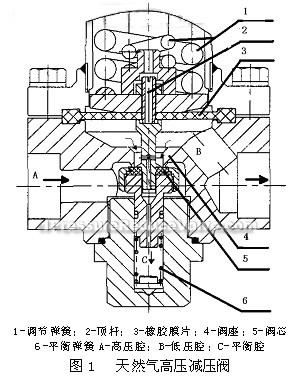
Natural gas high pressure reducing valve includes: valve core, valve seat, body, rubber diaphragm, balanced springs, adjustable spring, ejector, etc. as figure 1. In the whole device, pressure regulative spring, rubber diaphragm through the ejector acting on core force, balanced springs act on core force, the three are balanced, and composed by these components to constitute a closed-loop-conditioning systems. When the input gas reducing valve high-pressure gas pressure and flow change, or the output gas pressure and output flow change, core is destroyed by the force, moving up and down under the functions of rubber diaphragm, regulative springs and balanced springs, changing the throtting area between the core and valve seat, so as to maintain outlet pressure stability.
2 Modeling of high pressure natural gas reducing valve
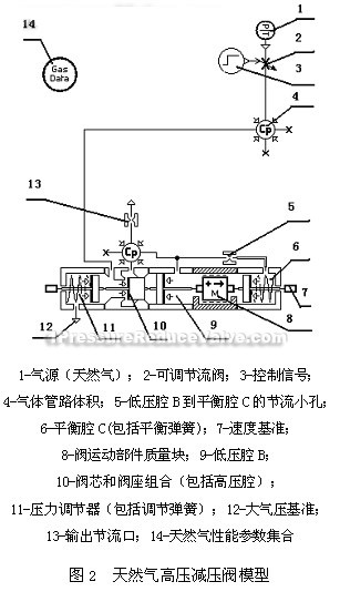
Natural gas high pressure reducing valve adopts AMESim software (Advanced Modeling Environment for Performing Simulations of Engineering System) for modeling, AMESim supplies a perfect and superior policy environment and the most flexible solution for the fluid power (fluid and gas), mechanical, thermal fluid and control system. Relative to the flow continuity equation based on the tradition, force balance built model, AMESim software modeling is more accurate and more practical. Model shown in Figure 2.
This model includes AMESim gas pressure, mechanical model library submodels. Based on natural gas high-pressure reducing valve particular physical structure, working principle, the phenomenon interested when researching and so on, to select simplified mathematical model. Model specific circumstances described as belows:
In the model, to provide parts 1,2,3 to form the ideal gas source and switching valves, through the setting, air source pressure changes within the range of 5-25Mpa, provide mapping static characteristic curve pressure source; through changing the 3 jumping time can provide drawing dynamic characteristic curve step pressure source. Part 13 provides the limited flow function in whole test process. Parts 5,6,8,9,10,11 compose the whole body of natural gas high-pressure reducing valve. Part 5 simulates the channel throttling function from low-pressure chamber B to balanced chamber C; Part 6 simulates balanced springs and ejector to form a closed balanced cavity C; Part 8 simulates the friction (including static friction, dynamic friction) between valve moving parts quality and themselves; part 9 simulates valve low-pressure valve chamber B (including rubber diaphragm and the push-rod); Part 10 simulates valve core and valve seat combination (including the high-pressure chamber A) through setting the size of the throttling port, we can accurately change the entire device throttling effect; Part 11 simulates the pressure reducing and regulating function of pressure regulative spring, this paper will adjust it to 1.17Mpa.
Need to explain that the additional components 5,6 function is simulating the effect of balanced cavity, the actual natural gas high-pressure reducing valve main spring force is instable, leading to the outlet end static pressure reset duplicated accuracy is worse when the reducing valve works, and under the case of rated high flow gas supply, reducing valve outlet pressure fluctuation is volatile. In actual natural gas high pressure reducing valve regulative springs use the composite spring, in order to simplify the model, it sets the part 11 adjustable spring parameters as a independent spring that is the same with the composite spring; Part 9 rubber diaphragm has no similar model in the AMESim Software model library, but because of the actual gas high pressure reducing valve uses the pressing plate structure, simplify the rubber diaphragm as a piston component when modeling; Part 10 because of existing a sealing material between the valve core and seat, and the seat is groove structure, that are not considered in the model, the phenomenon of leakage between them is ignored, sealing is ideal.
In short, in this model, without taking the gas leakage, parts heat transfer characteristics, pipe actual length into account, makes the whole model idealization. Set the simulated calculating time as 0.001S. air source adopts constant temperature and pressure CH4 source, the temperature is 303.15K. Atmospheres pressure is 0.1013MPa.
3. Model Simulation
To obtain this paper concerned natural gas high pressure reducing valve static characteristics, dynamic characteristics. Using AMESim Design exploration module function modules provided by AMESim software to reaserch natural gas high pressure reducing valve model.
In order to obtain the static characteristics of natural gas high-pressure reducing valve, first of all, setting input parameters, and simple output parameters in the AMESim export module, and then run the design exploration, create a new DOE project, then setting controls and responses operating parameters, finally, draw the main effect diagram.
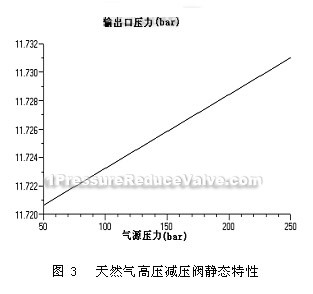
Static characteristics can describe synthetically the valve acting sensitivity, sealing and design rationality, these problems reflected design whether is reasonable and ultimately can reflect on the gas reducing valve outlet pressure devication sizes. Through setting the output throttling port hole diameter as 1mm, affecting as a limiting ring, changing the natural gas work pressure (5-25Mpa), and obtains the pressure changes in the output throttling port upstrean, thereby mapping out its static characteristic curve shown in Figure 3, from the graph, we can see it is with the minimum difference to setted value. Figure 3 downward trend shows, flow down and the pressure drops at the same time.
Dynamic characteristic is mainly describing natural gas high pressure reducing valve working stability, if the design is unreasonable, natural gas high pressure reducing valve will appear unstable vibration phenomenon in their working process, reflected in the outlet pressure produces substantially fluctuation, with severe noise, even makes component failed. Through setting simulated switch jumping time (3S later), you can get the response of the output throttling port upstream gas supply pressure mutations, shown in Figure 4. From the figure we can see that due to adding larger damping in the piston quality, which reduces the vibration of valve core. Figure 5 is under the small damping case, the output pressure occurs sharp vibration. In diagram we need to indicate that the downward trend happened before 2S, is due to when carrying out numerical calculations, in order to accelerate the operating speed, AMESim man-made turn off the function of calculating static operating point. It will not affect the overall computational accuracy. In Figure 4 and Figure 5, after the 3S, the emergence of a gentle slope is due to the output throttling port upstream exists a small closed volume, after the pressure mutation comes, it will produce short-term pressure drop within this region.
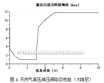
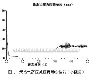
In fact, natural gas high pressure reducing valve expression in the static characteristic curve is more steep and in the model because of ignoring a considerable number of practical factors, such as valve internal leakage, etc. So, the model is more ideal in characteristic curve; in dynamic characteristic occurs the larger overshoot, because in the model, there are some minor disturbances ignored, only considered relatively simple coulomb friction, therefore it has some difference with the reality in the curve vibration, but not a lot.


