Air Filter Reductor
features
QFH type air filtration pressure reducing machine is one of the auxiliary devices of pneumatic instrumentation. air pressure from the air compressor 0.3 ~ 1Mpa, after filter and clean, is adjustable among 0 ~ 0.16, 0 ~ 0.25, 0 ~ 0.4, 0 ~ 0.6 Mpa any output pressure value within the scope, keep stable. As all kinds of pneumatic instrumentation and air pressure pneumatic device provide unit and other equipment fixtures.
structure and working principle
2.1 structure
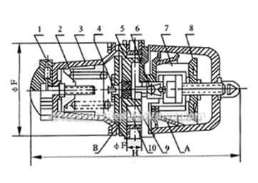
QFH type air filter pressure reducing machine structure, take the picture for example。
2.2 working principle
QFH type air filtration decompression machine is designed according to the principle of balance of power. When the pressure from the air compressor, after receiving input into filter (A) gas chamber in water, oil, dust. because given spring (3) the forces will open valve (7), which flows through ball valve and inflow the outlet pipe, through feedback catheter into feedback gas chamber (B), force on the pneumatic diaphragm (5) level off a balance with given spring. But due to the output pressure by load flow changes, the output pressure above or below a given value. As output pressure below a given value, diaphragm (5) with a force of spring force balance, the diaphragm, make the ball down move, the opening (7) of ball-valve more than originally, pressure compensation. As output pressure is higher than a given value, force on diaphragm (5) lost balance with given spring, diaphragm upwards, the valve stem (10) depart from diaphragm hard pistil (11), air pressure go into atmosphere through holes by the balance finally, thus output pressure has been stable at a given value.
Dimensions & constructral diagram

Air filter reductorreducing valve constructral diagram
Main technical performance
3.1 basic parameter and dimensions| type item | GFH- 111 | GFH- 211 | GFH- 212 | GFH- 213 | GFH- 221 | GFH- 222 |
GFH- 223 |
GFH- 241 | GFH- 261 | GFH- 263 | |||
| pressure of gas-supply | 0.3~0.7 | 0.4~0.7 | 0.5~1.0 | 0.7~1.0 | |||||||||
| max. outlet pressure MPa | 0.16 | 0.25 | 0.4 | 0.6 | |||||||||
| max. outlet flow m3/h standard state | 3 | 12 | 40 | 3 | 12 | 40 | 3 | 40 | |||||
| thread of connecting pipe | M10×1 | G1/2〞 | G3/4〞 | M10×1 | G1/2〞 | G3/4〞 | M10×1 | G3/4〞 | |||||
| installation dimensions | Install screw hole center distance mm | M6 | - | M6 | - | M6 | |||||||
| 25 | - | 25 | - | 25 | |||||||||
| dimensions (ΦF×H)mm | Φ70×165 | Φ70×165 | Φ100×225 | Φ120×240 | Φ70×165 | Φ100 ×225 |
Φ120 ×240 |
Φ70×165 | Φ70×165 | Φ70×165 | |||
3.2 working environment conditions
normal working conditions;
(1) temperature is -25~+55℃;
(2) relatively temperature is 5%~95%;
(3) vibration frequency is not more than25Hz, vibration swing ia not more than 0.5mm;
(4) there is no detrimental substance corrosive to the decompresion machine in air
Installation、Usage、 Maintain
4.1 installation
1 meter installation must abide by direction arrow, or press the "enter" and "output" pipe connection, and shall not mistaken, install is in the table, installation dimensions (install screw holes, the center distance mm).
2 the bottom of meter cover is a regulation, for water supply and sewage.
3 meters in normal conditions, not in use special maintenance, repair for six months, after filtering elements blocking, 10% rare hydrochloric acid boil half an hour, after drying can be restored to its blow gas flow characteristics.


